Autodesk RVT_ELEC_01101 Valid Dump, RVT_ELEC_01101 Latest Braindumps Book
Wiki Article
What's more, part of that PassTorrent RVT_ELEC_01101 dumps now are free: https://drive.google.com/open?id=1pYVUXrVf09cBKFfdXazPNRmi9bkLOgpJ
Autodesk certification RVT_ELEC_01101 exam is one of the many IT employees' most wanting to participate in the certification exams. Passing the exam needs rich knowledge and experience. While accumulating these abundant knowledge and experience needs a lot of time. Maybe you can choose some training courses or training tool and spending a certain amount of money to select a high quality training institution's training program is worthful. PassTorrent is a website which can meet the needs of many IT employees who participate in Autodesk Certification RVT_ELEC_01101 Exam. PassTorrent's product is a targeted training program providing for Autodesk certification RVT_ELEC_01101 exams, which can make you master a lot of IT professional knowledge in a short time and then let you have a good preparation for Autodesk certification RVT_ELEC_01101 exam.
One of the key factors for passing the exam is practice. Candidates must use RVT_ELEC_01101 practice test material to be able to perform at their best on the real exam. This is why PassTorrent has developed three formats to assist candidates in their RVT_ELEC_01101 Preparation. These formats include desktop-based RVT_ELEC_01101 practice test software, web-based practice test, and a PDF format.
>> Autodesk RVT_ELEC_01101 Valid Dump <<
100% Pass Quiz 2026 Autodesk High Hit-Rate RVT_ELEC_01101: Autodesk Certified Professional in Revit for Electrical Design Valid Dump
If you are looking to be Autodesk RVT_ELEC_01101 certified. PassTorrent is here to provide you with the best Autodesk Certified Professional in Revit for Electrical Design (RVT_ELEC_01101) exam dumps through which you can clear your Autodesk Certified Professional in Revit for Electrical Design (RVT_ELEC_01101) certification exam. We are providing practice exams in three formats including PDF which is the downloadable file from which you can study for your Autodesk Certified Professional in Revit for Electrical Design (RVT_ELEC_01101) exam questions and our Web-based application provides you the facility to assess yourself without installing any software on your device to prepare you for Autodesk Certified Professional in Revit for Electrical Design (RVT_ELEC_01101)exam dumps.
Autodesk RVT_ELEC_01101 Exam Syllabus Topics:
| Topic | Details |
|---|---|
| Topic 1 |
|
| Topic 2 |
|
| Topic 3 |
|
| Topic 4 |
|
| Topic 5 |
|
Autodesk Certified Professional in Revit for Electrical Design Sample Questions (Q58-Q63):
NEW QUESTION # 58
Refer to exhibit.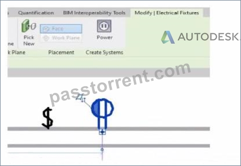
An electrical designer is circuiting a dwelling unit. The receptacle (electrical fixture) shown must be controlled by the switch (lighting device) shown to switch a plug-in lamp When the receptacle is selected, Revit does not provide an option to add the receptacle to a switch system.
What is causing this issue?
- A. The switch and the receptacle are not on the same circuit
- B. A switch system has not yet been created.
- C. The receptacle's "Switchable" option Is not selected within the family editor.
- D. Only lighting fixtures can be added to switch systems.
Answer: C
Explanation:
In Autodesk Revit Electrical Design, when an electrical designer attempts to control a receptacle (an Electrical Fixture family) with a switch (a Lighting Device family) as part of a switch system, Revit will only allow this connection if the receptacle's family has been configured as Switchable within the Family Editor.
According to the Autodesk Revit MEP User's Guide (Chapter 17 - "Electrical Systems"):
"Revit allows you to add elements such as lighting fixtures or receptacles to a switch system only if the family includes a switchable connector. The 'Switchable' parameter must be enabled in the Family Editor to allow this connection." This means that for the receptacle shown in the exhibit to appear as an available component for switching, the Electrical Connector within its family must have the Switchable property checked. This parameter is found under:
Family Editor → Select Connector → Properties Palette → Electrical - Data → Switchable.
If this option is not enabled, Revit treats the receptacle as a standard unswitched outlet and will not display it in the switch system creation dialog. Once the option is checked, the designer can reload the family into the project and associate it with a switch system normally.
Additionally, the Smithsonian Facilities Revit Template User's Guide explains this concept as follows:
"To associate receptacles with lighting switches, ensure that the receptacle family has a switchable connector. Without this setting, the device will not appear as an assignable component to a switch system." This distinction is important in residential electrical modeling, where switched receptacles are common for plug-in lamps. Lighting circuits can include both Lighting Fixtures and Switchable Receptacles when the family configuration supports it.
Incorrect Options Explanation:
A . A switch system not being created is irrelevant - the issue occurs before system creation.
C . Being on the same circuit doesn't affect switchability; it affects electrical load connection.
D . Incorrect - Revit supports switchable receptacles if properly configured.
Therefore, the correct answer is B. The receptacle's "Switchable" option is not selected within the family editor.
References:
Autodesk Revit MEP User's Guide - Chapter 17 "Electrical Systems," pp. 417-421 Autodesk Revit Electrical Design Essentials - Section "Creating and Editing Electrical Fixtures and Switch Systems" Smithsonian Facilities Revit Template User's Guide - Section 8.4 "Switchable Receptacle Family Standards," p. 89
NEW QUESTION # 59
How can an arrowhead be added to a lag leader line?
- A. Enable Leader Arrowhead in the instance properties.
- B. Choose an arrow type for the Leader Arrowhead in the Type Properties.
- C. Change the Leader Type to Free End.
- D. Select the tag and enable Leader Line in the Properties palette
Answer: B
Explanation:
In Autodesk Revit for Electrical Design, arrowheads on leader lines-such as those used with tags, text notes, or annotations-are controlled through Type Properties, not through instance properties or free-end options.
According to the Revit MEP User's Guide - Annotating Chapter (Chapter 47 and 42), the section "Modifying Tags" explains:
"Select the tag, and on the Properties palette, click (Edit Type). In the Type Properties dialog, select a value for Leader Arrowhead to add an arrowhead to the leader line." This confirms that the arrowhead is defined at the type level, meaning any change applies to all tags or text notes of that annotation type throughout the project. The Leader Arrowhead property allows the designer to choose from predefined arrowhead styles (like "Filled Arrow," "Dot," "Tick Mark," etc.), which are defined globally under:
Manage tab → Settings panel → Additional Settings → Arrowheads.
Furthermore, the document specifies under "Leader Arrowhead Properties":
"Sets the arrowhead shape on the leader line. The value is the name of the arrowhead style defined by the Arrowheads tool." This behavior applies to all annotation categories, including text notes, keynotes, material tags, and electrical device tags, maintaining consistency across all view types in an electrical project.
Therefore, Option C is the correct answer because arrowheads are configured via Type Properties, while the other options are inaccurate:
Option A (Free End) only defines leader attachment behavior.
Option B (Instance properties) does not include a "Leader Arrowhead" toggle.
Option D (Enable Leader Line) only adds or removes a leader line, not the arrowhead style.
References:
Autodesk Revit MEP User's Guide - Chapter 47 "Annotating," pp. 1040-1055 Autodesk Revit MEP User's Guide - Chapter 42 "Text Notes and Tags," pp. 936-949 Autodesk Revit Electrical Design Essentials - "Leader Arrowhead Properties and Annotation Standards"
NEW QUESTION # 60
Refer to exhibits.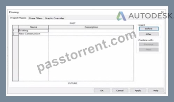
An electrical designer models an existing receptacle on an existing wall that the architect has indicated to be demolished.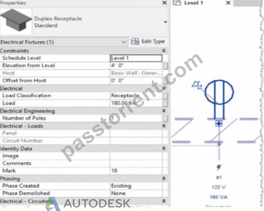
The view is intended to show demolition, and the view's Phase is set to New Construction. How should the designer indicate that the receptacle must also be demolished?
- A. Add a Demolition phase, then set the receptacle parameter Phase Demolished to Demolition.
- B. Set the receptacle parameter Phase Demolished to New Construction.
- C. Set the receptacle parameter Phase Demolished to Demolition.
- D. Set the receptacle's type parameter Match Phasing to Host.
Answer: B
Explanation:
In Autodesk Revit, phasing allows designers to track existing, demolished, and new elements across different project stages. Every model element includes two key phasing parameters:
Phase Created - defines when the element was built or introduced.
Phase Demolished - defines when the element is removed or demolished.
In the provided exhibits:
The project contains two phases: Existing and New Construction.
The receptacle's Phase Created parameter is set to Existing, indicating it belongs to the pre-existing building condition.
The architectural wall hosting the receptacle is to be demolished during New Construction.
When a view's Phase is set to New Construction and its Phase Filter is configured to show demolition, only elements whose Phase Demolished equals New Construction will appear as to be demolished. Therefore, the electrical designer must set the receptacle's Phase Demolished value to New Construction so that it graphically displays as a demolished element in the demolition plan.
As explained in the Autodesk Revit MEP User's Guide - Phasing and Coordination:
"Elements created in one phase and demolished in a subsequent phase must have their 'Phase Demolished' parameter set to that later phase to display properly in demolition views." Thus, to correctly coordinate with the demolition of its host wall, the receptacle must be flagged for demolition during New Construction.
NEW QUESTION # 61
An electrical designer needs to check for Interferences between conduit in the host model and beams in a linked structure model in the Interference Check dialog, select the items that the designer must select to perform the interference check. (Select two.)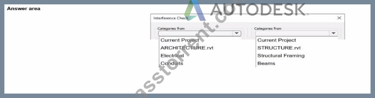
Answer:
Explanation: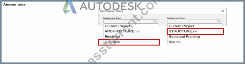
NEW QUESTION # 62
An electrical designer needs to add spaces to a model displaying the architectural room name and number. What should the designer do before creating the spaces?
- A. Use Transfer Project Standards to Import rooms from the architectural model.
- B. Select Room Bounding from the architectural link's type properties.
- C. Select Save Positions for the architectural links in the Manage Links dialog.
- D. Change the architectural model display settings to By Host View,
Answer: B
Explanation:
Before placing spaces in an MEP model that should reflect architectural room names and numbers, the linked architectural model must be set to Room Bounding. This ensures that Revit recognizes the architectural walls and room boundaries, allowing the spaces to reference and display room information correctly.
As the Revit MEP documentation explains:
"Turns on the Room Bounding parameter for the linked model. This step ensures that the Revit MEP project recognizes room-bounding elements in the Revit Architecture project."
"The spaces use the room boundaries defined by the Revit Architecture project." Additionally, the section Using Room Boundaries in a Linked Model details the procedure:
"In a plan view of the host project, select the linked model symbol → Click Modify | RVT Links tab ➤ Properties panel ➤ (Type Properties). In the Type Properties dialog, select Room Bounding." Once this setting is enabled, Revit MEP automatically detects the architectural rooms, enabling the designer to place spaces that inherit the architectural room name and number.
NEW QUESTION # 63
......
We are popular not only because we own the special and well-designed RVT_ELEC_01101 exam materials but also for we can provide you with well-rounded services beyond your imagination. We have an authoritative production team and our RVT_ELEC_01101 study guide is revised by hundreds of experts, which means that you can receive a tailor-made RVT_ELEC_01101 preparations braindumps according to the changes in the syllabus and the latest development in theory and breakthroughs.
RVT_ELEC_01101 Latest Braindumps Book: https://www.passtorrent.com/RVT_ELEC_01101-latest-torrent.html
- Review Key Concepts With RVT_ELEC_01101 Exam-Preparation Questions ???? Search for ➽ RVT_ELEC_01101 ???? and download it for free immediately on ⇛ www.pdfdumps.com ⇚ ????Best RVT_ELEC_01101 Practice
- Free PDF 2026 RVT_ELEC_01101 - Autodesk Certified Professional in Revit for Electrical Design Valid Dump ???? Search for ➠ RVT_ELEC_01101 ???? and download it for free on ☀ www.pdfvce.com ️☀️ website ????Testking RVT_ELEC_01101 Learning Materials
- RVT_ELEC_01101 Exam Questions Pdf ???? Exam RVT_ELEC_01101 Review ???? Valid RVT_ELEC_01101 Vce ???? Simply search for ✔ RVT_ELEC_01101 ️✔️ for free download on “ www.prep4away.com ” ????RVT_ELEC_01101 Valid Test Voucher
- Review Key Concepts With RVT_ELEC_01101 Exam-Preparation Questions ???? Enter ▶ www.pdfvce.com ◀ and search for ✔ RVT_ELEC_01101 ️✔️ to download for free ????Reliable RVT_ELEC_01101 Test Camp
- Free PDF 2026 High-quality Autodesk RVT_ELEC_01101 Valid Dump ???? The page for free download of ⮆ RVT_ELEC_01101 ⮄ on 【 www.examdiscuss.com 】 will open immediately ????New RVT_ELEC_01101 Test Labs
- Testking RVT_ELEC_01101 Learning Materials ???? Latest RVT_ELEC_01101 Exam Cram ???? Testking RVT_ELEC_01101 Learning Materials ???? Easily obtain free download of ➽ RVT_ELEC_01101 ???? by searching on ➠ www.pdfvce.com ???? ????Reliable RVT_ELEC_01101 Exam Registration
- RVT_ELEC_01101 Reliable Test Review ???? Reliable RVT_ELEC_01101 Exam Registration ???? RVT_ELEC_01101 Reliable Test Review ???? Open website ▷ www.easy4engine.com ◁ and search for ( RVT_ELEC_01101 ) for free download ????RVT_ELEC_01101 Exam Questions Pdf
- Pass Guaranteed Quiz 2026 Autodesk RVT_ELEC_01101: Valid Autodesk Certified Professional in Revit for Electrical Design Valid Dump ???? Open website ⇛ www.pdfvce.com ⇚ and search for “ RVT_ELEC_01101 ” for free download ????RVT_ELEC_01101 Latest Test Materials
- Reliable RVT_ELEC_01101 Exam Registration ???? Exam RVT_ELEC_01101 Success ❎ New RVT_ELEC_01101 Test Labs ???? The page for free download of 「 RVT_ELEC_01101 」 on “ www.prepawaypdf.com ” will open immediately ????RVT_ELEC_01101 New Dumps Ebook
- Free PDF 2026 High Pass-Rate Autodesk RVT_ELEC_01101: Autodesk Certified Professional in Revit for Electrical Design Valid Dump ???? ➤ www.pdfvce.com ⮘ is best website to obtain ( RVT_ELEC_01101 ) for free download ▛RVT_ELEC_01101 Latest Test Materials
- Pass Guaranteed Quiz 2026 Autodesk RVT_ELEC_01101: Valid Autodesk Certified Professional in Revit for Electrical Design Valid Dump ???? Immediately open ( www.troytecdumps.com ) and search for ➽ RVT_ELEC_01101 ???? to obtain a free download ????RVT_ELEC_01101 Exam Questions Pdf
- aadamnrwk045099.nizarblog.com, roxannsxut085129.blogrenanda.com, mppshop.net, tiannatvvy356367.hazeronwiki.com, berrylearn.com, montycins511726.wikimidpoint.com, nicolasczcy234401.blogrelation.com, www.stes.tyc.edu.tw, sashakjto069681.blogitright.com, totalbookmarking.com, Disposable vapes
BTW, DOWNLOAD part of PassTorrent RVT_ELEC_01101 dumps from Cloud Storage: https://drive.google.com/open?id=1pYVUXrVf09cBKFfdXazPNRmi9bkLOgpJ
Report this wiki page